Thursday, May 11, 2017

Wetland Flight Near Tomah

Introduction

        On May 10th the UAS class met in Tomah to work on some research and development work on a wetland just outside of the city. The purpose of the flight was to get a baseline to look at the changes in vegetation that will occur over the next few months. Follow up flights will be done using a red edge in an effort to see what types of vegetation are where on the property. The goal of the flights is to be able to market the property to a business that can re purpose it as a wetland. 

Figure 1
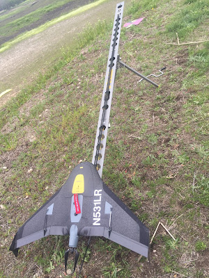
        Figure 1 above shows the Trimble UX5 prepared to launch.


Figure 2
         Figure 2 above shows the Trimble UX5 in the carrying case. Peter Menet of Menet Aero brought the drone and executed the flight. Peter went over the pre flight check list with the class and allowed with assisting him as well. 


Figure 3
        Once the UX5 had completed its flight, professor Hupy and the class put up the DJI M600 with the rededge sensor. Above is the Real Time Kinematic (RTK) that was used to assist in real time corrections to assist with accuracy during the flight. Figure 4 below shows the tablet and controller that were used during the flight.


Figure 4
        Figure 5 below is a photo of the M600 right before flight.


Figure 5

Monday, May 8, 2017

Ponds and Community Garden Near South Middle School Eau Claire


Introduction


        On Tuesday May 2nd was the first opportunity the class had to get out and see some UAV's in action. The DJI Phantom 3 advanced was flew first to collect the nadir images along with some oblique imagery of the students cars parked on site. Next, the DJI Inspire was flown to give the class an opportunity to try it out, no data was collected using that platform. This lab taught students how to collect GPS coordinates for the GCP's that were made in the previous lab. The GCP locations were collected using a $12,000 survey grade GPS and combined with the UAS data to increase spatial accuracy of the data.

Study Area

        Figure 1 below is a number of maps that show the study area for the data collection in this exercise. The area of interest (AOI) is located to the south of the Eau Claire South Middle School, just to the north of Pine Meadow Golf Course, and to the southeast of the corner of Mitchell Avenue and Hester Street. Data collection took place on May 2nd, and the conditions were partly cloud with a steady wind at 5mph with gusts up to 10-12 mph. In addition to the community garden area picture in figure 1, the ponds just to the south of the community garden was also flew.

Figure 1


Methods


         Figures 2, 3, and 4 below show a close up of the survey grade GPS that was used to obtain sub centimeter accuracy for this lab. The device is not hard to use, but there is a large amount of settings and useful features that do take some time to become comfortable with. The survey grade GPS was used to get a coordinate at sub centimeter accuracy, to be used with the UAS flight that was done a different day. The GCP's were created the week before the flights and the creation of them can be viewed in the previous blog. The GCP's that were previously laid out in the garden were left for this flight and the rest of the GCP's were spaced evenly across the road from the garden around the ponds. The survey grade GPS was again used to collect the coordinates for the GCP's. The coordinate system used was UTM WGS 1984 Zone 15N. After creating a new file for data collect the points of the GCP's can be collected by simply pressing one button.


Figure 2
       When using the survey grade GPS it is important to make sure that the level is accurate as pictured in figure 2 above. If the bubble is out of the circle it could hinder the data accuracy. After the data collection button was pressed it is essential to not move the GPS at all because the location will be altered then.

Figure 3
         Figure 3 above shows how the GPS unit was set up on the GCP's, it was carefully centered in the middle of the X before the data collection was started. Also the GCP's were collected in order from 1 to 16 to ensure that they were given the correct location when adding in the UAS flights.

Figure 4
        Figure 4 above is a close up of the screen that is attached to the shaft of the GPS unit, it is all pretty self explanatory to set up. Always be sure to check the coordinate system before data collection.

Figure 5
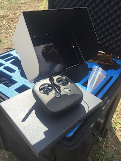
         Figure 5 above is the remote and tablet used to fly the DJI Inspire and figure 6 below is a picture of the DJI Inspire that was flown for fun and to get the class some experience flying.

Figure 6


Figure 7
       Figure 7 above is the Real Time Kinematic (RTK) used in sync with the m600 to better data accuracy during the flight in real time. Figure 8 below shows the remote and the tablet used during the flight.


Figure 8
       Figure 9 below shows the DJI M600 used to generate the orthomosaic and DSM with hillshade that are pictured in figures 10 and 11.

Figure 9


Results

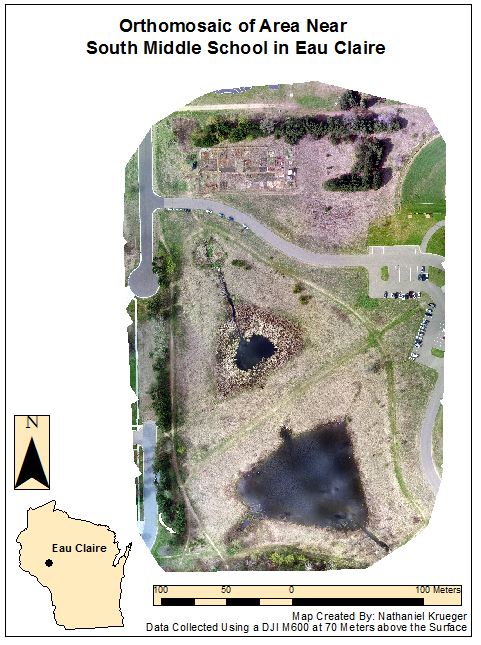
        Figure 10 below is an orthomosaic that was generated from the flight of the M600 over the garden and the pond to the south of South Middle school. The ortho is very high resolution and allows the viewer to get a good idea of the vegetation around the area. The image is very high resolution and the difference in the plot in the community garden should be noted. Also on the far right in the northeast corner, half of the left field of the baseball field is visible. The southern most pond is well over 6 times the size of the northern most pond.
Figure 10
        Figure 11 below shows a orthomosaic with a digital surface model and hill shade that was generated in ArcMap. This does a nice job of showing the changes in elevation throughout the area of interest. In the northeast corner the elevation is notably the highest, this makes sense because this is where the baseball and softball fields are located. The trail between the two ponds in the middle of the map shows that the trail is elevated in comparison to the ponds, obviously to make the trail passable. The ponds and the areas immediately around the ponds are a pretty dark blue, meaning that they are lower elevations than the majority of the rest of the map. To create the map below the transparency of the orthomosaic was set to 50% and the DSM was overlaid with the hill shade tab checked in ArcMap.

Figure 11


Conclusion

       In conclusion, it was a welcomed relief for the class to get out and do some real world flying and to then process the data after collecting it. The class created the GCP's, put them out, collected the GPS coordinates, assisted in the flight and processed the data, showcasing all of the skills that were learned throughout the semester. Over $20,000 dollars of equipment was used for this lab, showing that the class knows how to fly a number of different drones as well as how to operate the survey grade GPS for GCP coordinates collection.

Monday, May 1, 2017

Ground Control Point (GCP) Production

         The purpose of this weeks lab was to create GCPs for use at a later date at a place in Tomah, Wisconsin. The GCPs were made of a heavy duty black plastic that does not rot as plywood does, this increases the life of the GCPs. Other materials used include pink and neon spray paint, a stencil made of plywood, sheets to protect Professor Hupy's garage floor and a table saw. The plastic came in large black sheets and they were cut into 2 foot by 2 foot sections. The stencil was placed on one side, sprayed with pink and allotted time to dry, then the other side was done and a number was added with the neon green. In total 16 GCPs were made and the entire process took just over a half hour.

        A ground control point is a point of the earth that has a known geo-referenced location. They are used to ensure data accuracy and integrity and they are commonly used when taking photos using a UAV or other aircraft. Equally spaced out GCPs can drastically increase the accuracy of aerial map generation for a specific area of interest. Figure 1 below shows the first GCP that was created, while figure 2 displays how the class worked together doing many different steps at the same time. Figure 3 shows all of the 16 finished products and finally figure 4 shows some spray paint skills from a classmate that says "UAS."


Figure 1: Example of GCP
Figure 2: Creation of GCPs

 
Figure 3: Class photo after completion
Figure 4: Artistic ability of a Classmate 


Monday, April 24, 2017

Mission Planning

Introduction


          The purpose of this lab is to get some experience with the mission planning software called C3P. Along with how the mission planning software works, other essentials of planning a successful mission will also be discussed. Using a mission planning software helps increase the accuracy of a drone flight and does not require the pilot of the drone to do the entire flight by hand. This mission planning software allows the user to manipulate every variable that affects the flight. The altitude and the spacing of the grid which is the resolution can both be set, as well as a specific flight area. The lower the flight is conducted at, the higher the resolution, additionally flight time will increase as well. If the flight is done at a high altitude, the resolution will decrease as will flight time. In this lab, two areas will have test mission flight areas done. Area one will be Bramer Test Field, the second will be a pond that is located in Dunn County to the East of the City of Menominee. Throughout the lab, the limitations of C3P will be discussed, as well as an overall review and final thoughts of the software. 

Mission Planning 

          Prior to departing for the mission there is a number of different variables to account for, that if neglected could end the flight before it starts. The first step is to know the study area, it is important to know what obstacles could be in the area, as well as the general layout of the surface. It is good to do this in order to know if a cell signal will be available if the tablet being used depends on a cell signal. On a different note, it is important to know if there will be crowds in the area watching the flight, if so the operator must be very careful as it is illegal to fly over a crowd. The terrain is essential because it will dictate how the flight is done, the drones need room to turn around and if there is a hill, trees, telephone wire, cell towers or other obstructions that will dictate altitude the planner will want to know about that before showing up for a job. Additionally, weather checks prior to getting to the flight area are important, windy and or rain could delay or even stop the flight. On the mechanical side of things, always be sure that batteries are charged and that all of the equipment is in top functional shape. 

         Upon arriving at the field there are still a number of things to check off before beginning the flight. In order to select a safe home, takeoff and rally point the weather must be checked again. The current weather as well as weather conditions for the future should be noted and factored in. The wind speed, wind direction, temperature, and dew point should be recorded. Additionally, a detailed look into the vegetation of the area will be beneficial to unsure that there are no obstacles that did not show up when doing the initial planning in the office. The drone must always take off into the wind and also land into the wind, going with the wind could cause the user to lose control and to damage or lose the drone all together. A correct elevation must be taken, as the drone will be flying at a specific altitude to ensure data integrity. One final issue to take note of is the possibility of electromagnetic interference such as power stations, power lines, or underground metal or cables. Be sure to make it clear to the team what units are being used, metric is preferred as it is best for simple conversions. The final step before flight is to make sure the cell signal is established and not going in and out and the mission should be reevaluated to make sure every variable is correct. Figure 1 below shows the mission settings and how all of the variables can be changed to adjust for the flight area.

Figure 1

C3P

Get to Know the Software

          The C3P software is started by selecting the points for home, takeoff (T), rally (R) and land (L). These locations will be different for each study area, and depend mainly on the wind direction and strength. Different maps can be used, the default from C3P, ArcMap or even google maps, it is almost always best to use a map that displays imagery to get an idea of the terrain. Next, a flight can be made using the draw tool, the draw by area is the most commonly used way to set up a flight area. The mission settings can be set up however the remote operator sees fit. The mission settings include altitude, speed, overlap, sidelap, GSD (pixel resolution) and the type of camera used and overshoot. The altitude used is determined by the desired resolution, as well as making sure the drone will clear any obstacles in the flight path, so it is important to calculate a correct absolute altitude. As a rule of thumb the speed should be 16-18 m/s. There should be overlap of 80% of more, as well as 70% side overlap to ensure the flight has good accuracy. The overshoot can also be changed and it is important to make sure that the drone will not hit anything when overshooting to correct itself. Certain land features such as hills or mountains can dictate the direction of the flight because the drone may be able to overlap one way, but not the other. 


Figure 2

  
        Figure 2 above shows the flight with the altitude at 100 meters, and figure 3 below shows the flight at 200 meters. Figure one shows that there will be issues with the path of the drone as shown by the bright orange on the right side. Additionally, the figure 3 shows that there will be no issues. If there are red circles as shown in figure 2, be sure to increase the altitude or to slightly vary the flight path. 


Figure 3
           When working with different altitudes it is important to make note of the differences in altitude types within the software. Absolute altitude is the height the aircraft is above the terrain it is flying over. In contrast, true or relative altitude is the actual height above mean sea level.

Figure 4
         Figure 4 shows a flight path using the draw tool with street points, that allow the drone user to fly along a linear feature such as the road depicted. The 3D view shown is from ArcGIS and this allows for the pilot to see the types of terrain and vegetation around the flight area. Be sure when running a flight similar to this that the drone being used has the battery life to make a successful flight. 


Figure 5
         Figure 5 above shows the area to the west of the city of Menominee Wisconsin which is a pond in the middle of an 80 by 80 acre field section. The pond is roughly 60 acres and holds good duck numbers throughout the year. If the land owner wanted to get an elevation map made as well as a more detail high resolution map this would be an option. The planning software did not account for telephone poles that are on the land, though they may be very new because they are not shown on the aerial imagery from ESRI.


Figure 6
          Figure 6 shows the area of the flight. The silos in the upper left had to be avoided as well as to the upper right hand corner. It was tough to get the correct positions for things because the circles were bound to have some overlap. The area is surrounding by roads, making it a little tight, though if this were done in real life there is plenty of field to deal with home and take off and landing. The flight needed to be run with the overshoot being north and south because there is more free space to the north and south of the pond. 
Review

         Without a question this mission planning software is much more convenient than having to calculate and write down all the variables by hand. The fact that the software shows the user where the drone will hit if the altitude is low enough is really nice. This software can be a little bit sophisticated when first starting so just as in ArcMap, the use of help was very beneficial. There is so many nice features in this program. Having the flight time accounted for from the battery life is key to time management. Additionally, the software can update for the weather conditions, this takes even more stress off the operator. With that being said, this is still a man made software that could be inaccurate. Pilots of these flights should always double and triple check every variable of the flight and I would also urge that they stay attentive at all times in case the altitude was not correct or the wind changes. Also when working on my own location for a flight the mission software did not account for the silos that were located in the upper left, also I had the square larger and flying under 25 meters. With my previous knowledge I knew that there would be issues with telephone poles, but the software did not register that. 


Monday, April 17, 2017

Processing Oblique UAS Imagery Using Image Annotation

Introduction

       In previous labs throughout the semester the imagery used has been in a format called nadir. Which is when the camera is at a position that it is pointing directly down, meaning the location of the images is above the target. A camera pointing to the nadir direction means that it is vertical or perpendicular to the ground. Nadir imagery is used for creating orthomosaics and digital surface models using Pix4D.
      In this lab, the aerial images used that were were oblique imagery. Oblique imagery is aerial photography that is taken at a 45 degree angle from the ground or the object that is the subject of the flight. The 45 degree angle enables users to be able to measure the entire object, rather than just the top of the object as in nadir imagery. Using oblique imagery is applicable in the geospatial market because it allows for the creation of 3D models and it allows for measurements of the sides of structures along with the top. Oblique imagery is used in urban planning, crisis management, and it also has a variety of other applications.

Methods

        The purpose of this lab is to use a process called annotation in Pix4D to get the fundamentals regarding processing and correcting oblique imagery. Image annotation is used to remove all the discrepancies around an object so that the subject of the imagery is more accurate. After the initial processing in Pix4D is complete the annotation toolbar can be accessed by clicking on the ray cloud and then selecting an image on the left hand side for annotation. Next click the pencil icon on the right hand side which will allow the user to begin annotation. Make sure the annotation method is mask, then the entire image was annotated by clicking on the areas that were not what was wanted for the 3D model. After everything by the target is annotated, click apply and repeat the process until all angle are covered. After the number of images annotated is sufficient, be sure to click the advanced tab under processing options and the use annotations tab under point cloud and mesh. Then uncheck initial processing and select the point cloud and mesh and process the data with annotations. After completion turn off the cameras and click on the triangle mesh tab, this will generate the 3D model. The same process described above was used for all three image sets.
         There are three types of annotation that can be used, mask, carve, and global mask.  In this lab the mask form of annotation was used. Mask annotation removes the background around the subjects. Not every image needs to be annotated because there is considerable overlap between the images. Throughout this lab three different oblique aerial image sets were used in an effort to create 3D models of each. The initial images were processing with and without the annotation to see if there were significant differences.
        After Pix4D is open the first image set was added, the work space was set up correctly and the camera model was changed to linear rolling shutter. From there the model that was selected was the 3D model. This is important to note because in previous labs the 3D map was used, if the 3D map is selected the processing will be very slow and there will be errors when trying to begin the annotation process. This change is done because there will be no orthomosaics or DSM's created, but rather a 3D model the shows all the angles of the subjects of the flight.
         The first image set that was worked with was a bulldozer that was located at the Litchfield Mine to the southwest of Eau Claire. The second imagery set that was used was a shed that is located on the property of Eau Claire South Middle School. The third imagery set is of Professor Hupy's now retired Toyota Tundra in the parking lot near Eau Claire South Middle School parking lot. Each of these oblique imagery sets were taken by a DJI Inspire, the UAV flew in a tornado pattern around the subjects, in an effort to capture all angles of all sides. Figure 1 below shows how the drone was flew in an effort to cover all of the angles. The flight for the truck is shown, though the other two flights looked much the same. Each image set will be described in more detail below.

Figure 1: Flight Pattern

Bulldozer


         Figure 2 below shows an annotated image of the bulldozer at the Litchfield mine. It is easy to see all of the little spots that are indented on the bulldozer, these are hard areas to get accurately, though as shown below it can be done.


Figure 2


Shed at South Middle School

       Figure 3 below shows an annotated image of the shed at south middle school. The white dashes at the bottom of the image can be tough to get so be sure to zoom in, also the shadow on the left of the image need to be done carefully, as the software may consider the shadowed part of the building the same as the shadow on the ground.  


Figure 3


Pickup Truck

         Figure 4 below shows an annotated image of the Toyota Tundra that was done in a parking lot. Make note of how hard the tires are to annotate and be sure they are done accurately, also be sure the bumper and mirrors are not selected as they are important to making an accurate 3D model.


Figure 4


         The rematch and optimize tool was used on each of the data sets to see if that would better the results. The conclusion that made was that the rematch and optimize is not necessary as there was no notable improvement. Also this process can take some time depending on the size of the image set, so there was no need for the wasted time with this additional step.
        After spending many hours doing the annotation process a few tips can be offered. Making circles is an effective way to cover a lot of ground. Also clicking and holding the cursor means the annotation process in continuous. Start at the outside of the image and work in, be careful not to get to close to the object when holding the mouse because a large part of the object could get selected and then the eraser will have to be used.


Results

          Below are screen captures that show multiple angles of each of the image sets. Each one will be discussed in more detail individually. Ultimately each image set still had flaws from the background of the images, and that will be discussed below. In these setting the image annotation was still morphed from the background, though the tool set of being able to eliminate the backgrounds of images for 3D model creation is an essential tool to have. Also one of the first things to be done right before annotation is to increase the size of the box used for annotating. This helps creates larger pixels and makes the process go much quicker.

Bulldozer

        The bulldozer was by far the most challenged image set to annotate. There was a lot of nooks and crannies that are very challenging to annotate correctly. This was the first set that was done, and that was done because this was the trial run to get a feel for how things worked. Five images were annotated here. Figures 5-7 are the output images after the annotation and figures 8 and 9 show the bulldozer with no annotation. The differences are not notable, even on closer inspection, zoomed very far in there are minuscule differences at best. This is unfortunate to see due to the time that was spent annotating.

Figure 5: Annotated

Figure 6: Annotated

Figure 7: Annotated

Figure 8: Not Annotated

Figure 9: Not Annotated

Shed at South Middle School

         The shed at south middle school went quite a bit smoother and faster than the other two data sets. the shadows that were cast caused a few issues, and also the lines on the track and the fence posts were hard to get at some points, that can be remedied by zooming in, but not zooming in so far that the software breaks up the smaller areas into tiny pixels. For this image set 15 images were annotated because the process went very quickly. Along with increased annotation, the rematch and optimize was done to see if the output quality would be better. By doing more images, one would believe the quality would increase, again, unfortunately there was not a lot of improvement from the images with no annotation. One difference that can be noted is that were is less of a pix elated look on the annotated image. Though the there is still the error on the peak of the shed. Also the sides are a little more clear on the annotated image.

Figure 10: Annotated

Figure 11: Annotated

Figure 12: Annotated
Figure 13: Not Annotated

Figure 14: Not Annotated


Pickup Truck

         Annotated the Toyota Tundra was slightly more difficult than the shed at south middle school but not nearly as tough as the bulldozer. The mirrors and fender flares caused some issues as the software had a difficult time differentiating between the ground and those objects, also the bumper kept wanting to be selected when it was not supposed to be. Again, just the same as the two previous data sets there was not a notable difference from the image set that was annotated and the one that was not.

Figure 15: Annotated

Figure 16: Annotated

Figure 17: Annotated
Figure 18: Not Annotated

Figure 19: Not Annotated


Conclusion

          After completion of this lab it would be easy to assume that annotation of oblique imagery is not necessary, though most of the time it is. All in all it certainly does not hurt the quality of the data set and any improvement of data quality that can be done should be. Oblique imagery does a nice job of creating a 3D model of structures. After completing this exercise it would be recommended that if a large image set needs to be annotated the job could be outsourced to a different company. This is due to the large amount of time that it takes to do the annotations and the fact that it can be very stressful when things get annotated that were not intended to get annotated. Other issues with annotation were the shadows, clouds, and little objects such as the dashes on the track at south middle school, the mirrors and fender flares on the truck, and most of the dozer because there was not many straight lines, but rather a considerable amount of intents that had to be dealt with. When annotating it was found that it is important to do images from each angle around the subject being annotated. Doing this will cut down on the number of images that need to be annotated because there will be alot of overlap with other images if the angles selected are correct. Also for whatever reason some images just do not cooperate, if an image is being hard to annotate it is recommended to just try a new image.

Sources

https://pix4d.com/support/
Monday, April 10, 2017

Calculating Volumetrics Using UAS Derived Data

Introduction

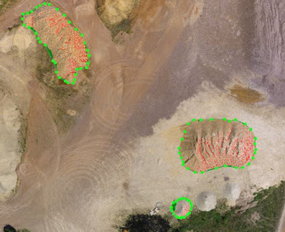
          Volumetric Analysis is the study of volumes of objects using aerial imagery. Volumetric Analysis is used often in Unmanned Aerial Systems, as well as in other aspects of geography such as remote sensing. This application has many uses, it can be used to calculate the volume of anything from buildings to natural features.It is important to note that in order to do this analysis x,y and z values are needed to get an accurate measurement. The images used throughout this lab were captured by a DJI Phantom 30 and they were collected with high overlap, allowing for the creation of a Digital Surface Model. The use of ground control points in this lab also adds to the accuracy of the volumetric analysis. To the southwest of Eau Claire is the Litchfield Mine site, this location has been used in several exercises during the semester. For this lab three sand piles were selected at random and a volumetric analysis was completed on them using Pix4D, 3D Analyst and by running a TIN. There was a number of tools used in this lab including the volumes tab in Pix4D, the extract by mask and surface volume tool for 3D analyst and finally the Raster to TIN, Add Surface Information and Polygon Volume for the TINs. After the calculations were done using three different methods a table including the three values and there averages was generated along with multiple maps.

Methods

        The first method used was the volumetric analysis in Pix4D. The project that was used in lab 5 which was the Litchfield Mine with GCP's was used. On the far left under the Volumes tab the user can draw points around the sand piles and by simply clicking calculate the volume of the pile in meters cubed is provided. 

Figure 1
           Figure 1 above illustrates the three piles that were used in this lab. The pile on the far right is pile 1, pile 2 is in the upper left hand side and pile 3 is pictured on the bottom right. Volumetrics is interesting because upon an initial glance pile 2 looks to be the largest, though pile one is significantly larger in actual area, and that will be discussed further in the results section. Figure 2 shows that pile 2 is more than a third smaller than pile 1. This is a very fast method to get the volume, it is efficient and very accurate.


Figure 2

         The second and third methods used to calculate the volume of the sand piles were both in ArcMap. There are other ways as well, but for the purposes of this lab two were selected, being 3D Analyst which calculates using the digital surface model and TIN, which is done by creating a TIN from the surface. First a new geodatabase was created and there were three feature classes created that were used for piles 1,2, and 3. Next using the editor tool bar polygons were created of each sand pile. Next the Extract by Mask tool was used to clip the areas that were just created from the DSM. Next the Surface Volume tool was used to get the volume of the sand piles.

         The third and final method used was the use of TINs's to calculate volume. The clips that were made in method two were used in the Raster to TIN tool which was found in the ArcHelp search bar. A TIN is generated from the raster, from there the Add Surface Information tool was used to get the elevation values for the TIN. After running the Add Surface Information tool a new layer is created in the results tab on the far left, after adding the layer to the map, the volume values are available by looking at the attribute table. The final step here is to use the Polygon Volume tool, this tool uses the TIN and the value that was just recorded in the previous step.

Results

          Figure 3 below is a table that displays the different volumes recorded for each pile along with the average of each method. Each of the methods are reasonably close to each other. The 3D analyst and TIN values were significantly closer that that of Pix4D, this can be easily explained by the fact that the data in ArcMap came from drawing polygons again, so there was a slight variability from Pix4D. When looking at pile three, there is not much difference between the three, this is because that pile was very symmetric, it was nearly a perfect circle, whereas piles 1 and 2 were very irregularly shaped. Another factor that would account for piles 1 and 2 having a greater variability is the fact that they were much larger, therefore there is more room for error when drawing the polygons.

Figure 3

         Figure 4 below is a map showing the changes in elevation of each of the piles. Each pile has a peak, which makes sense because that is how sand piles are made. Pile 1 is purple, pile 2 is red and pile 3 is purple at there highest elevations. This is important to note that pile 2 appears larger than pile 1, though pile 1 is over 400 meters cubed larger than pile 2. Those values are clearly depicted above by figure 3.

Figure 4
          Figure 5 below is a map that shows the full extent of the Litchfield mine to give perspective to the size of the pile compared to the overall size of the mine. As talked about previously, pile 2 had much less volume than pile 1, though they appear nearly the same size. Pile 3 was very small as it was over 55 times smaller than pile 1.


Figure 5


Conclusion

          After completing this lab it is easy to see all of the applications of volumetric analysis. The ways that were used in this lab were just three of the many ways these calculations can be done. Without question Pix4D is by far the quickest method, there is no actual baseline of what the actual sizes of the piles are, so it is not possible to tell which method was the most accurate. The TIN and 3D Analyst both used the same polygons that were drew, and calculated values using the same DSM, this accounts for there similarities at least in part. Even the slower methods of volumetric analysis are much faster than a company paying for someone to manually collect these values.